G10 The bench test was wrong (Tolerance stack-up)
Most hardware founders think a thorough bench test means the design is validated. It usually means your sample happened to be a lucky one.
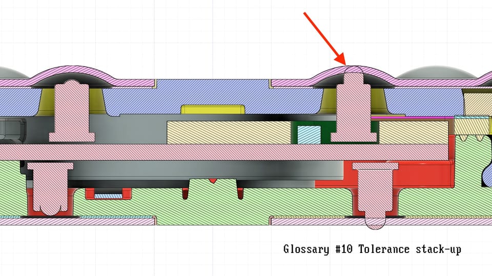
We used spring-loaded pogo-pins to make electrical contact with a concave surface inside a product enclosure. The vertical tolerance stack-up was done carefully: pogo-pin travel range, compression force at various depths, manufacturing variation on the cavity geometry. Everything checked out on paper and passed on the bench.
What we missed entirely was the horizontal axis.
Three separate sources of horizontal drift were stacking up against us, and we did not account for any of them:
- How the two enclosure halves locked together, with intentional play constrained by a gasket once closed, but not zero
- PCBA positioning inside the enclosure, where centering pins held the board but with some play of their own
- SMT placement tolerance for the pogo-pins on the PCB
Each source was small. Combined at worst case, they shifted the pin far enough off-center to contact the angled sidewall of the cavity instead of the bottom.
That angled surface converted the vertical spring force into a lateral component. The pogo-pin was pushing itself sideways using the energy of its own spring. Over weeks of daily enclosure flexing cycles, that constant lateral load broke the pogo-pin off its contact pad on the PCB.
Units passed factory testing because the failure was progressive. A freshly assembled unit worked fine on the line even with the pin slightly off-center. The damage accumulated over time in the field.
Tolerances do not fail where you calculated them. They fail where you forgot to.
The fix: redesign the contact surface to be flat and wide enough that worst-case horizontal drift still lands the pin well inside the pad area. No angled sidewall, no lateral force, no progressive damage.
This was not a knowledge gap, it was a process gap. The team had the skills to run a full multi-axis stack-up and accelerated life test at boundary conditions. The validation plan simply did not require it.
Tolerance stack-up checklist (use before design sign-off):
- For every interface, list every part and every process step that contributes to final position, on every axis
- Stack all sources at worst case simultaneously, not one axis at a time and not one source at a time
- At every interface, ask: what happens when position shifts to the edge of the tolerance window? Force vectors change, contact areas shrink, seal gaps open, things that nominal assembly will never show you
- Build boundary samples by shimming, offsetting, or selecting parts at worst-case dimensions, then run life tests on those, not on nominal units
- If your end-of-line gate is a pass/fail functional check, it will not catch progressive or wear-out failures, that needs a separate reliability test at boundary conditions